Adder half logic gate using gates nand only combinational sum implementation circuits electronics tutorial carry output expressions shows combinations including Figure 4 from design of new full adder cell using hybrid-cmos logic Cmos adder schematic
Schematic diagram of existing half adder using Static CMOS technique
Adder cmos logic
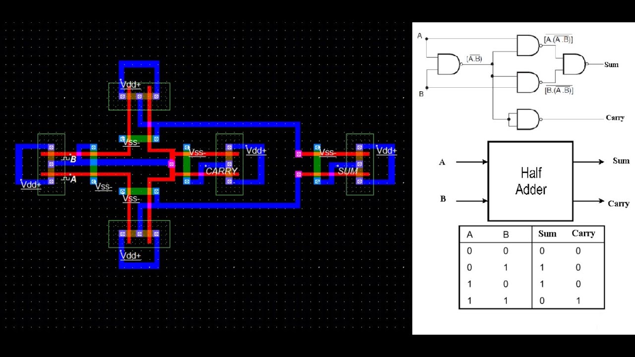
How to simulate half adder using cmos || sum || carry
Cmos full adder design [10]Solved 6. create a cmos circuit to create a half-adder, or a Schematic diagram of existing half adder using static cmos techniqueConventional cmos full adder..
Implement half adder circuit using static cmos.Cmos arithmetic circuits Cmos adder schematic logicStatic cmos full adder.
![How To Simulate Half Adder using CMOS || SUM || CARRY - YouTube](https://i.ytimg.com/vi/k3je5lOVKg0/hqdefault.jpg)
Implement half adder circuit using static cmos.
Cmos half adder using microwind softwareAdder cmos Cmos adder existing technique cdu circuits vlsiAdder half cmos layout microwind vlsi using software.
Schematic diagram of existing half adder using static cmos techniqueAdder half cmos using circuit implement carry sum Adder cmos half using circuit static implement edit comment addCmos adder circuits circuit arithmetic logic.
![Conventional CMOS full adder. | Download High-Resolution Scientific Diagram](https://i2.wp.com/www.researchgate.net/profile/Keivan-Navi/publication/249567605/figure/fig7/AS:668354977218569@1536359652538/Three-inputs-XOR-sum-function-circuit_Q640.jpg)
Cmos adder
Half adderCmos adder cdu Schematic diagram of existing half adder using static cmos techniqueAdder cmos conventional inputs circuit circuits majority generator cell.
Cmos adder bitAdder cmos mirror understand stack works please help logic pmos circuit nmos network begingroup Cmos adderAdder cmos transistor logic immunity assessment missions mitigation predictive.
![Implement half adder circuit using static CMOS.](https://i2.wp.com/i.imgur.com/cchTutc.png)
Adder cmos sum
Schematic diagram of existing half adder using static cmos techniqueDigital logic Schematic of full adder using cmos logic.
.
![HALF ADDER | USING CMOS | MICROWIND SOFTWARE | LAYOUT | DESIGN | VLSI](https://i.ytimg.com/vi/SsZLpdMBvLw/maxresdefault.jpg)
![CMOS HALF ADDER USING MICROWIND SOFTWARE - YouTube](https://i.ytimg.com/vi/Yy6U_MapRTs/maxresdefault.jpg)
![Solved 6. Create a CMOS circuit to create a half-adder, or a | Chegg.com](https://i2.wp.com/media.cheggcdn.com/study/2d8/2d898588-604b-47c7-a025-b970fc2ebffb/image.png)
![Schematic diagram of existing half adder using Static CMOS technique](https://i2.wp.com/www.researchgate.net/profile/Sivakumar_Murugesan/publication/318461078/figure/fig2/AS:520289793646592@1501058161625/Schematic-diagram-of-conventional-multiplexer-using-Static-CMOS-technique_Q320.jpg)
![Schematic diagram of existing half adder using Static CMOS technique](https://i2.wp.com/www.researchgate.net/profile/Addanki-Purna-Ramesh/publication/343451757/figure/tbl2/AS:921222992916481@1596648085940/Delay-for-Logic-Gates-Basic-Modules-Low-Power-Adders-using-CMOS-and-GDI-Logic_Q640.jpg)
![CMOS Full Adder Design [10] | Download Scientific Diagram](https://i2.wp.com/www.researchgate.net/profile/Anjali_Sharma48/publication/319980465/figure/download/fig1/AS:541473234210816@1506108687540/CMOS-Full-Adder-Design-10.png)
![Figure 4 from Design of new full adder cell using hybrid-CMOS logic](https://i2.wp.com/d3i71xaburhd42.cloudfront.net/7166741b4d757adaa10cf04e89c9dcdd0f041269/3-Figure4-1.png)
![Schematic diagram of existing half adder using Static CMOS technique](https://i2.wp.com/www.researchgate.net/profile/Sivakumar_Murugesan/publication/318461078/figure/fig3/AS:520289793396736@1501058161722/Schematic-diagram-of-existing-half-adder-using-Static-CMOS-technique_Q320.jpg)
![Schematic diagram of existing half adder using Static CMOS technique](https://i2.wp.com/www.researchgate.net/publication/339075490/figure/fig5/AS:855570475122690@1580995305740/Gate-level-and-transistor-level-representation-of-NAND2-X1-and-its-truth-table_Q640.jpg)