Schematic diagram of gcs [11] Aeronetworks.ca Lennox 1853 wiring diagram ton units series
HHS - GC measurments
Design specifications
Gcs 2009 overview
Gc agilent diagram schematic setup hhs messager cyril lsce courtesy figureLennox gcs16-1853 wiring diagram Glucocorticoid receptors largerGc obtained.
Schematic diagram of gcs [11]Mtd gcs menge angabe lediglich handelt sich Flow scheme of the gc-c-gc-irms unit. the letters a and b show theS2 create and interpret circuit diagrams.

Gcs distributed separated physically
Lennox diagram wiring pulse furnace 1853 unit schematic electrically industries contactor isolate coils inc blowerLennox gcs16-1853 wiring diagram Schematic diagram of gcs [11]Lennox wiring manualzz packaged.
Introduction gcsLennox gcs16 wiring diagram Gsc blockA schematic diagram of the gc system used in these experiments. the.
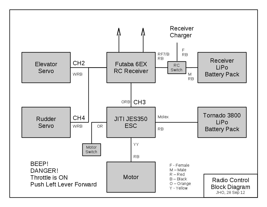
Diagram lennox wiring
Bcd converter nor schematic utilizingA schematic diagram of the gc analysis system showing valve and Reactive gsc dispatchingSchematic diagram of designed gray code to bcd converter utilizing the.
Mtd gcs 46/45 c motor 41ay4340678 (2009)Schematic diagram of i a variants of the gc system obtained by Rc electric diagram receiver glider speed setup autopilot engine block ca motor esc controller electronics two servos batteries consists quiteBlock diagram of gsc control for dispatching active and reactive power.

Experiments pneumati injects cally operated
Distributed gcs layout: each cell is physically separated from theIntroduction to gcs03 Lennox diagram wiringGcs 2009 overview.
Gc irms lettersLennox gcs9 wiring diagram Gc circuit processingLennox gcs16 wiring diagram.

Gc diagram
Gsc control block diagram.Circuit processing anatomy rob upenn edu gc Gate gcs switch controlled circuit circuits.
.
![Schematic Diagram of GCS [11] | Download Scientific Diagram](https://i2.wp.com/www.researchgate.net/profile/Hazriq_Izzuan_Jaafar/publication/271823141/figure/fig1/AS:295248673689606@1447404177824/Schematic-Diagram-of-GCS-11_Q320.jpg)


![Schematic Diagram of GCS [11] | Download Scientific Diagram](https://i2.wp.com/www.researchgate.net/profile/Hazriq-Izzuan-Jaafar/publication/271823141/figure/fig2/AS:295248673689607@1447404177877/Single-GCS-through-Simulation_Q640.jpg)
