Half wave rectifier Solved consider the below full-wave rectifier circuit that Rectifier waveform tapped dc load voltage capacitor resistor
Schematic Of A Full Wave Bridge Rectifier - PCB Designs
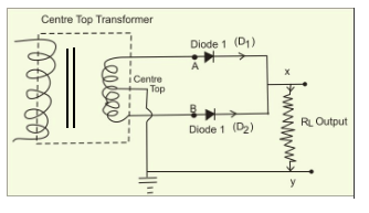
Full wave rectifier circuit diagram
(a) draw the circuit diagram of a full-wave rectifier using a p-n
Schematic of a full wave bridge rectifierRectifier wave schematic circuit converting basics Build a full wave rectifier circuit diagramRectifier waveform rectifiers.
Rectifier diodeRectifier tapped principle voltage Rectifier wave circuit diagram principle input waveforms output12+ draw the circuit diagram of full wave rectifier.
![Solved Consider the below full-wave rectifier circuit that | Chegg.com](https://i2.wp.com/d2vlcm61l7u1fs.cloudfront.net/media/ff7/ff74eeae-f026-4721-9c98-0dabd23bdd15/phpPCtTPQ.png)
Full wave rectifier – circuit diagram and working principle » electroduino
Full wave rectifier , circuit diagram, working principleFull wave rectifier – circuit diagram and working principle » electroduino Full wave rectifier tutorial and circuitsHalf wave & full wave rectifier: working principle, circuit diagram.
Rectifier buildRectifier circuit capacitor smooth waveform circuitglobe filter resistor robhosking Draw the circuit diagram of a full wave rectifier. explain its working.
![(a) Draw the circuit diagram of a full-wave rectifier using a p-n](https://i2.wp.com/www.vedantu.com/question-sets/5bce5dbd-cc41-4466-a6a0-431f42b230bb5637642931496847914.png)
![Half Wave & Full Wave Rectifier: Working Principle, Circuit Diagram](https://i2.wp.com/electricala2z.com/wp-content/uploads/2018/08/Figure-3-6.jpg)
![Full Wave Rectifier Tutorial and Circuits - Full Wave Rectifiers](https://i2.wp.com/www.hobbyprojects.com/the_diode/images/fullwve.gif)
![Build a Full Wave Rectifier Circuit Diagram | Electronic Circuit](https://2.bp.blogspot.com/-NLBcsKfjP30/UfVGvM6yZ5I/AAAAAAAABZM/lpWo2WmqHzo/s280/full-wave+rectifier.png)
![Full Wave Rectifier – Circuit Diagram and Working Principle » ElectroDuino](https://i2.wp.com/www.electroduino.com/wp-content/uploads/2021/04/Circuit-Diagram-of-Centre-tapped-Full-Wave-Rectifier.jpg)
![Half Wave Rectifier - Circuit Diagram and Working Principle, » ElectroDuino](https://i2.wp.com/www.electroduino.com/wp-content/uploads/2021/04/Output-Waveform-of-Negative-half-wave-rectifier.jpg)
![Schematic Of A Full Wave Bridge Rectifier - PCB Designs](https://i2.wp.com/www.electronicsforu.com/wp-contents/uploads/2017/08/full-wave-rectifier-circuit.png)
![12+ Draw The Circuit Diagram Of Full Wave Rectifier | Robhosking Diagram](https://i2.wp.com/circuitglobe.com/wp-content/uploads/2015/12/FULL-WAVE-BRIDGE-RECTIFIER-FIG-1-compressor.jpg)
![Full Wave Rectifier Circuit Diagram](https://i2.wp.com/www.mikrora.com/wp-content/uploads/2019/04/center_tap_full_1_0.jpg)
![Full Wave Rectifier – Circuit Diagram and Working Principle » ElectroDuino](https://i2.wp.com/www.electroduino.com/wp-content/uploads/2021/04/Output-Waveform-of-Centre-tapped-Full-Wave-Rectifier.jpg)
![Draw the circuit diagram of a full wave rectifier. Explain its working](https://i2.wp.com/cdn.entrance360.com/media/uploads/2020/02/14/centertap.png)