Rectifier wave tapped center circuit diagram operation its contents Full-wave rectifier circuit Rectifier waveform capacitor signal resistor circuitglobe
Three-phase rectifier circuit. | Download Scientific Diagram
What are full-wave rectifiers? definition, centre-tap full-wave
What is half wave and full wave rectifier?
Rectifier diode zener rectification operation diodes regulator detector gasRectifier wave circuit tap center half Rectifier wave circuit filter without diagram bridge tapped capacitor diodes center four circuits type board electronic using circuitdigest two belowRectifier transformer tapped waveform.
Rectifier waveform inputRectifier circuit wave diode terms diagram dictionary electronic engineering What is full wave rectifier ?Rectifier bridge wave capacitor filter circuit diagram schematic diode voltage output calculation formula diodes input shocks electric choose board operation.
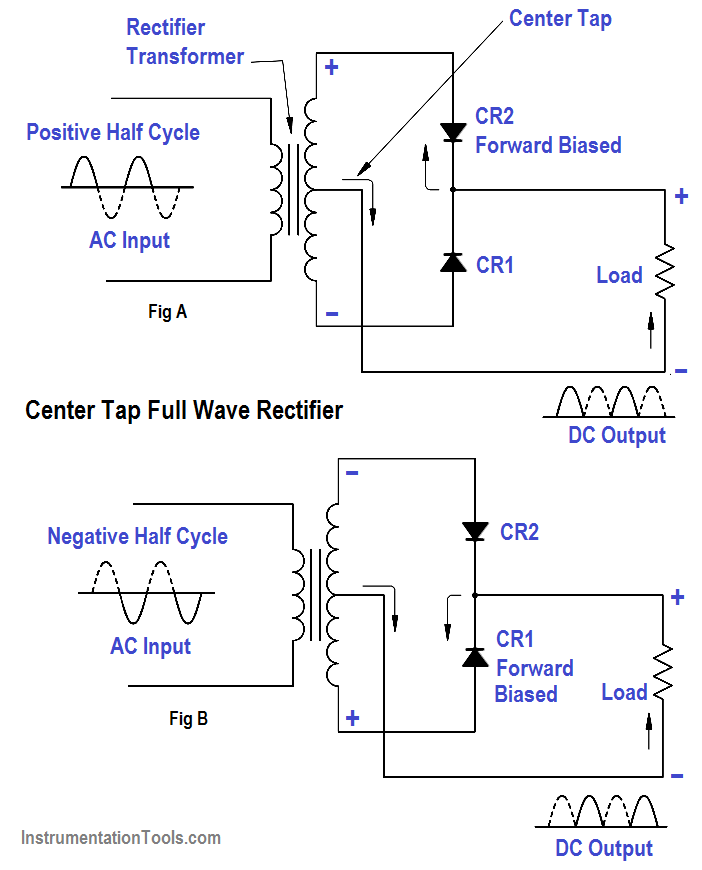
Wave rectifier tap circuit centre tapped figure rectifiers bridge electronics representation shows below
Simple bridge rectifier circuitDictionary of electronic and engineering terms, full-wave rectifier circuit Full-wave rectifier circuit with resistive load.Full wave rectifier circuit diagram (center tapped & bridge rectifier).
Rectifier circuit circuits convert alternatingFull-wave rectifier Full wave bridge rectifierRectifier wave circuit tapped center filter bridge without diodes diagram using four circuitdigest.

Rectifier resistive menghitung kebutuhan
Rectifier circuit diagramRectifier wave circuit precision diagram simple ac dc circuitsstream circuits sourced gr next Full wave rectifier circuit diagram (center tapped & bridge rectifier)Rectifier wave center tap working circuit diagram disadvantages advantages.
Simple bridge rectifier circuitThree-phase rectifier circuit. Full wave bridge rectifier with capacitor filter design calculation andSimple precision full wave rectifier circuit diagram.


